

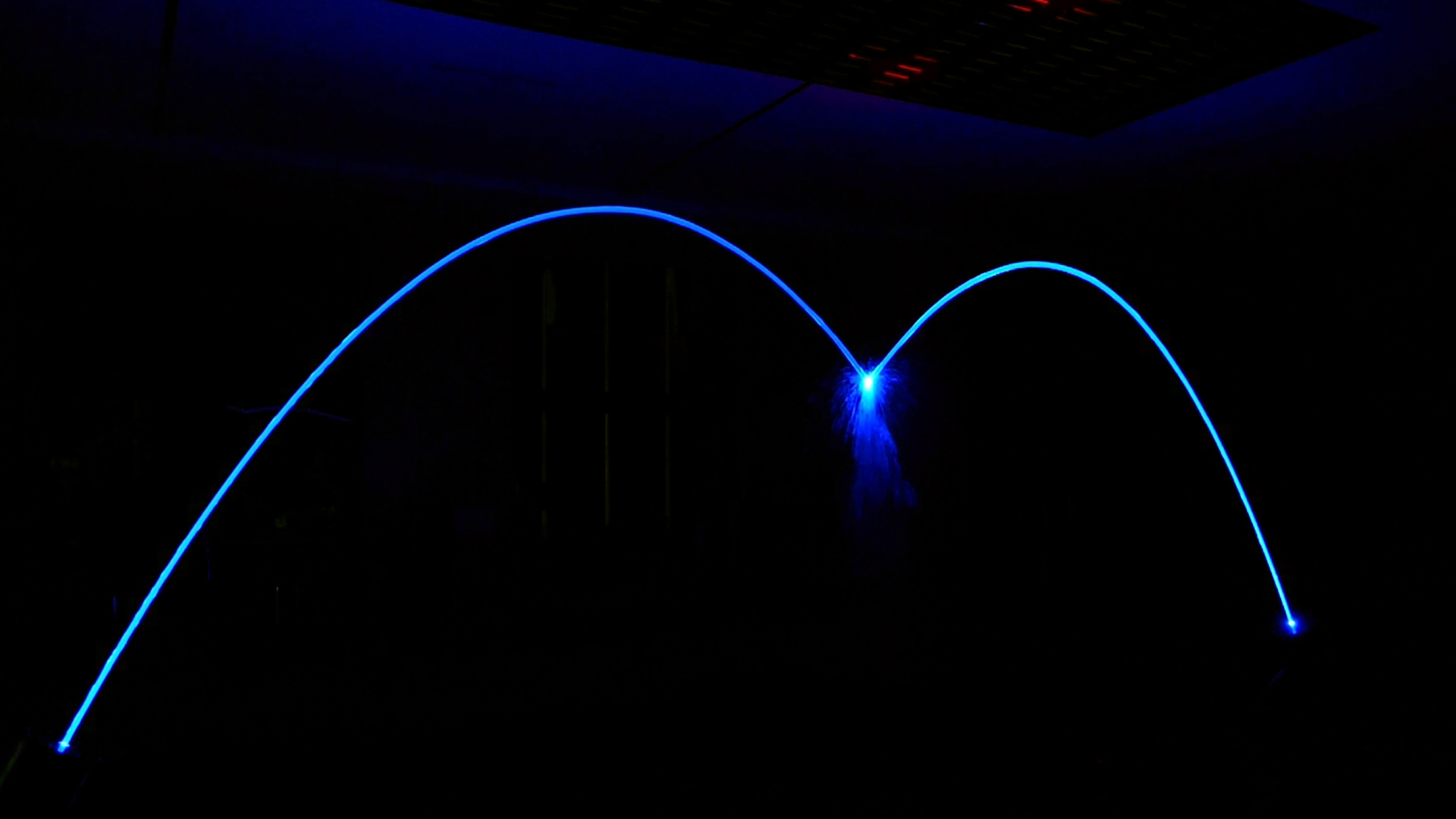
A smooth, glass-like fountain jet is not produced by water pressure alone. Its appearance depends on the flow conditions inside the nozzle, the stability of the water as it leaves the outlet, and the disturbances it encounters in the air.
Reynolds number (Re) is a useful starting point for understanding these conditions. However, it cannot predict the visual quality of a laminar fountain jet on its own. Nozzle design, upstream turbulence, surface tension, and operating conditions must also be considered.
This article explains how Reynolds number is calculated, why conventional pipe-flow limits need careful interpretation, and what engineers should examine when designing laminar and jumping fountain jets.
What Is Reynolds Number in Fountain Hydraulics?
Reynolds number is a dimensionless quantity that describes the relationship between inertial and viscous effects in a flowing fluid.
In simple terms, it helps engineers understand how a flow behaves under a given combination of velocity, characteristic dimension, and fluid viscosity.
For water flowing through a circular pipe, the Reynolds number is commonly used to distinguish between laminar, transitional, and turbulent flow.
| Reynolds number | Conventional pipe-flow classification |
|---|---|
| Below approximately 2,000–2,300 | Laminar |
| Approximately 2,300–4,000 | Transitional |
| Above approximately 4,000 | Turbulent |
These ranges are approximate guidelines for internal pipe flow. The exact transition depends on inlet disturbances, pipe geometry, and operating conditions.
They should not be used as universal acceptance limits for the appearance of a fountain jet after it leaves the nozzle.
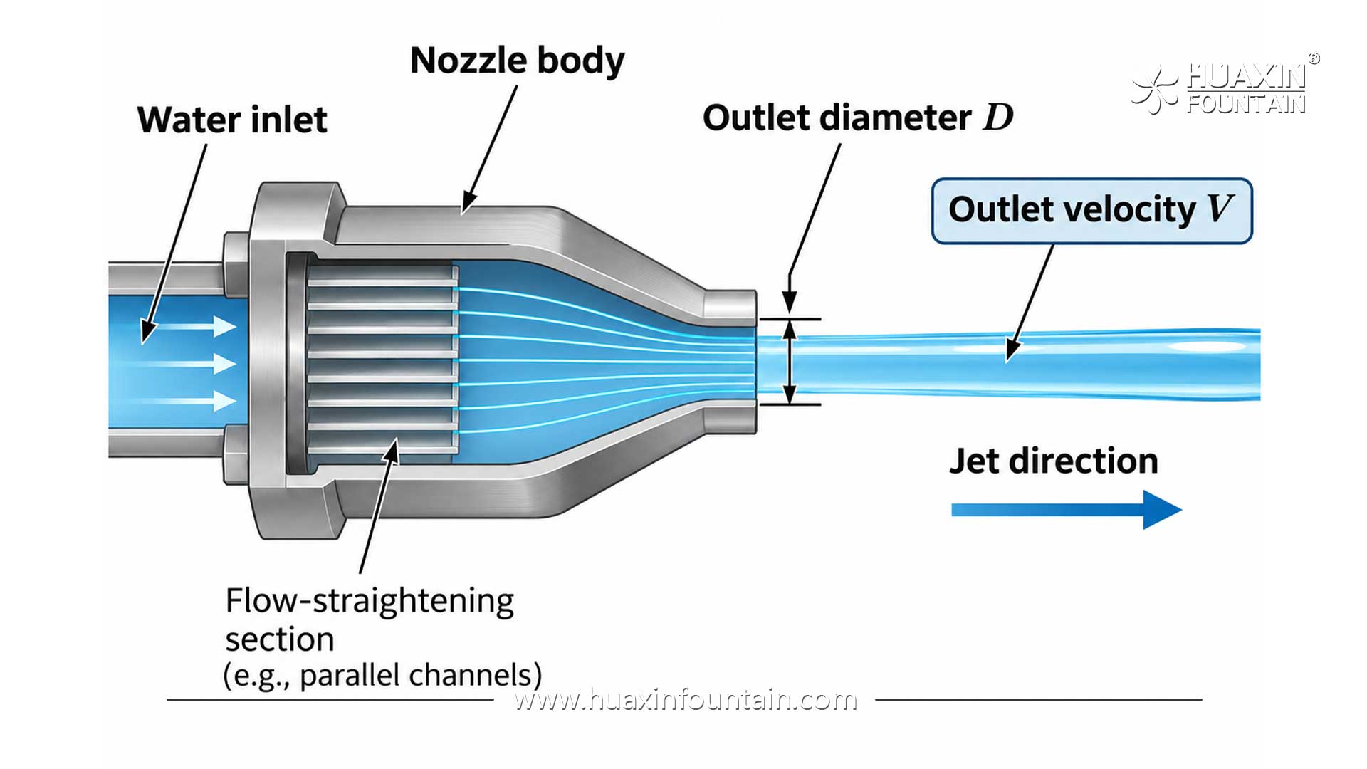
A fountain nozzle involves more than fully developed pipe flow. Water passes through internal passages, changes direction or cross-section, and finally becomes a free jet surrounded by air.
The resulting water surface is affected by conditions that a single Reynolds number does not fully describe.
How to Calculate Reynolds Number for a Fountain Jet
The commonly used equation is:
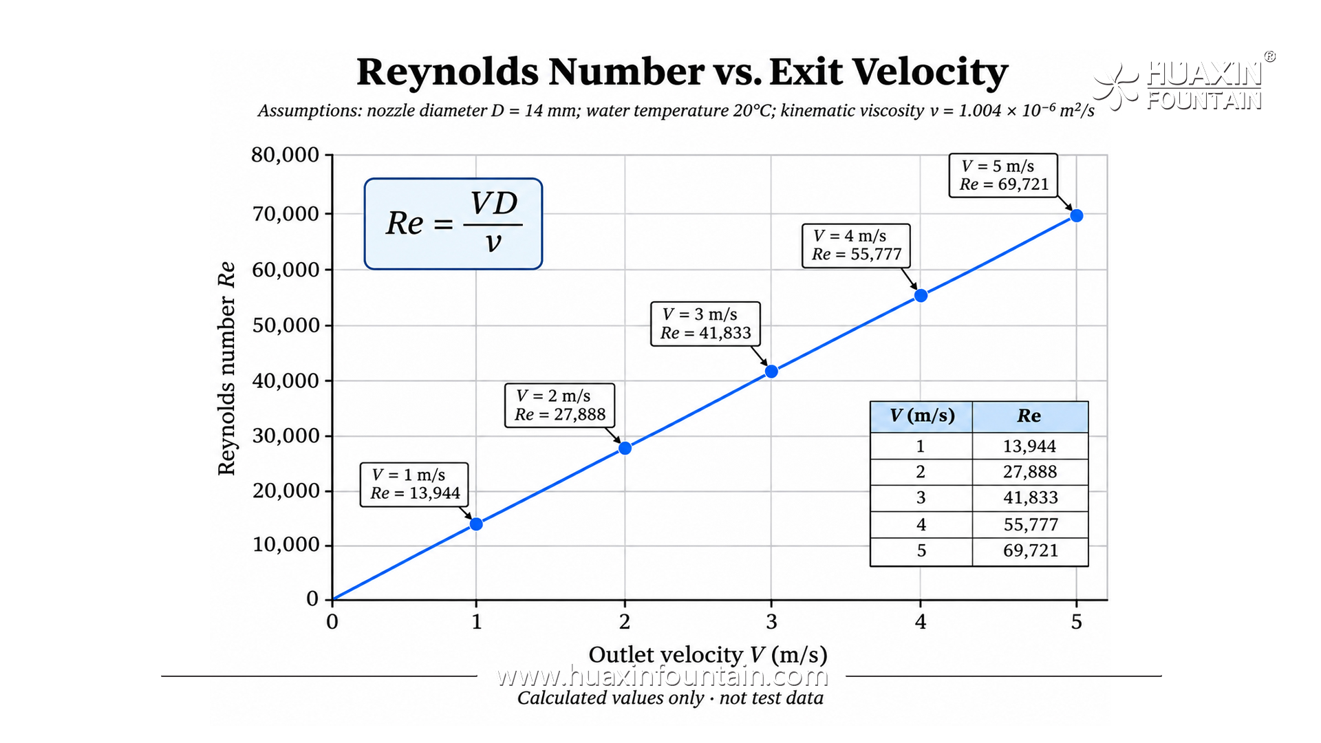
Re = VD / ν
An equivalent form using dynamic viscosity is:
Re = ρVD / μ
Where:
Re = Reynolds number (dimensionless)
V = mean water velocity (m/s)
D = characteristic diameter (m)
ν = kinematic viscosity of water (m²/s)
ρ = water density (kg/m³)
μ = dynamic viscosity of water (Pa·s)
For an approximately circular water jet, the nominal outlet diameter can be used as the characteristic diameter for an initial calculation.
At 20°C, the kinematic viscosity of water is approximately:
ν = 1.004 × 10⁻⁶ m²/s
When using this equation, all quantities must have consistent units.
An important distinction is that the nozzle inlet connection diameter is not necessarily the jet outlet diameter. Using a DN40 inlet connection for a nozzle with a 14 mm outlet would give an incorrect estimate of the outlet Reynolds number.
A Practical Calculation: 14 mm Fountain Jet
Consider an illustrative nozzle operating under the following conditions:
| Parameter | Value |
|---|---|
| Water temperature | 20°C |
| Jet outlet diameter | 14 mm (0.014 m) |
| Mean outlet velocity | 5.0 m/s |
| Kinematic viscosity | 1.004 × 10⁻⁶ m²/s |
Substituting the values:
Re = (5.0 × 0.014) / (1.004 × 10⁻⁶)
Re ≈ 69,700
For a single, filled circular outlet, the corresponding theoretical flow rate is:
Q = (πD² / 4) × V
Q ≈ 2.77 m³/h
This example uses assumed operating conditions for illustration. It is not a measured performance result for a particular Huaxin nozzle.
The calculated Reynolds number is far above the conventional laminar pipe-flow range.
Does this mean the water must immediately turn into spray?
Not necessarily.
The calculated value indicates the relative strength of inertial and viscous effects. It does not, by itself, tell us how smooth the jet surface will appear or how far the stream will travel before breaking apart.
The initial velocity distribution, internal disturbances, nozzle geometry, and surrounding air conditions also influence the result.
Why a Low Reynolds Number Is Not Enough to Guarantee a Glass-Like Jet
Some traditional fountain design references describe a Reynolds number below 500 as a favorable condition for obtaining a transparent, laminar-looking water column.
A low Reynolds number may indeed be associated with orderly flow under certain conditions. However, Re below 500 should not be treated as a universal requirement for commercial laminar fountain equipment.
Consider the previous 14 mm outlet example.
To keep its Reynolds number at 500 at 20°C, the mean exit velocity would have to be approximately 0.036 m/s.
Such a low velocity would provide very little momentum for producing a substantial water arc.
Practical fountain designs need sufficient exit velocity to reach the specified height and landing point.
This creates an important distinction between two ideas:
Hydraulic Flow Classification
A scientific description of the motion of fluid, based on defined conditions and measurable flow parameters.
Visual Jet Coherence
The visible continuity and surface smoothness of a water column as it travels through the air.
A coherent stream can exist over a finite distance even when its Reynolds number is higher than the range conventionally associated with laminar pipe flow.
This does not mean that the flow is necessarily laminar in the strict scientific sense. Nor does it mean that turbulence can be ignored.
It means that the Reynolds number must be interpreted alongside the physical conditions of the actual nozzle and jet.
Studies of water jets have shown that upstream flow conditions and nozzle geometry can strongly influence surface disturbances and the distance over which a jet remains intact.
For fountain engineering, the required outcome is not simply a low calculated Reynolds number. It is a sufficiently smooth and stable water arc under the intended operating conditions.
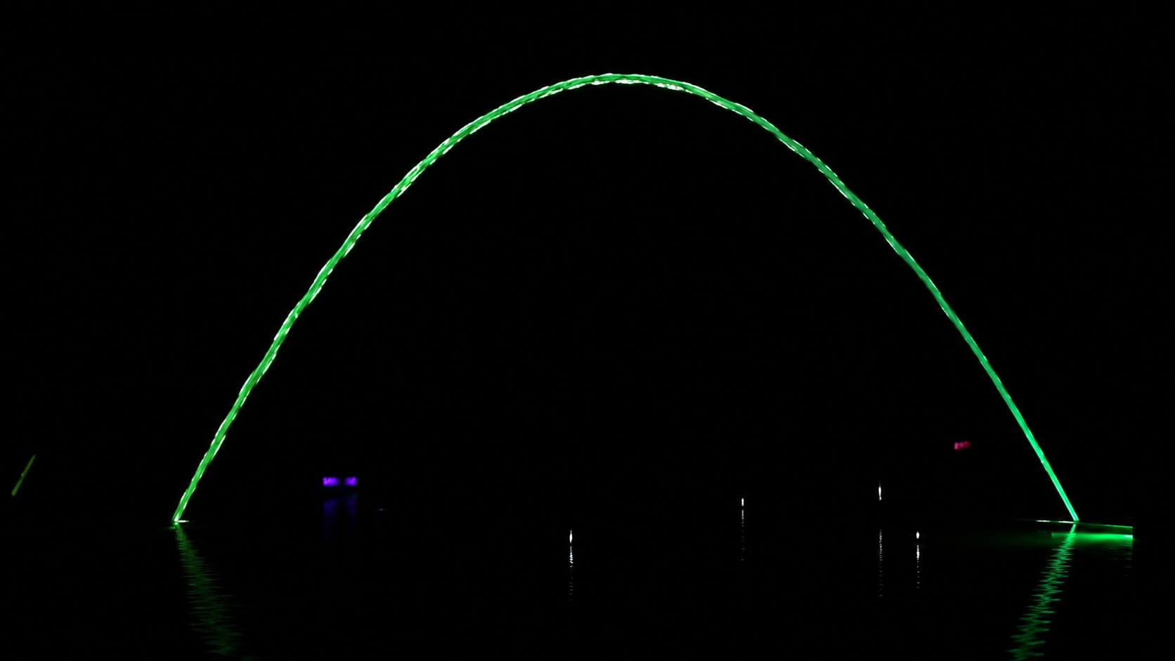
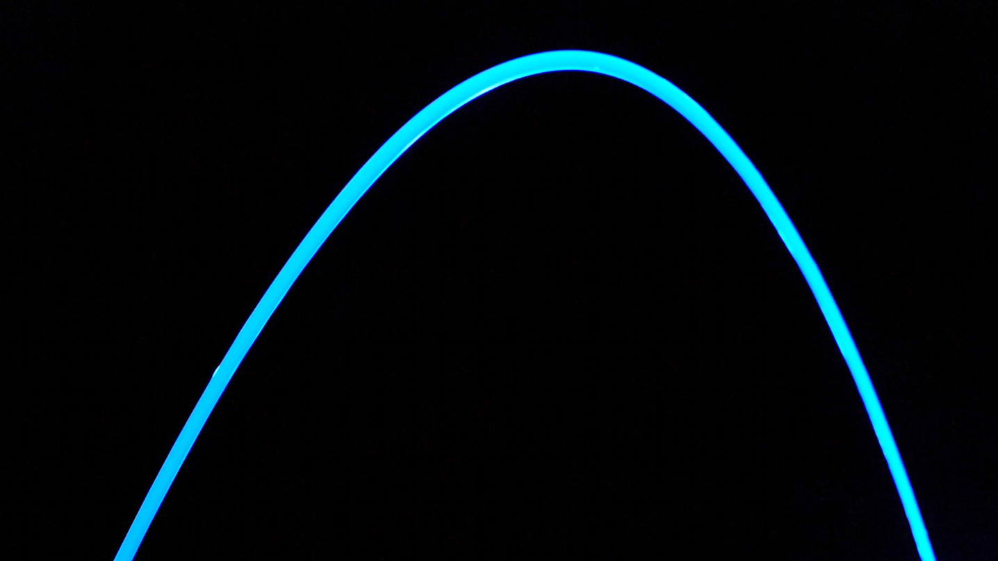
Comparison of a smooth, coherent water arc and a visibly disturbed water stream. Images are for visual illustration, not a controlled hydraulic test.
What Actually Determines Laminar Fountain Jet Quality?
Several factors influence whether a fountain jet retains its glass-like appearance.
1. Flow Conditioning Inside the Nozzle
Water supplied by a pump may contain velocity fluctuations, swirling motion, and disturbances created by bends, valves, and other components.
A laminar fountain unit is designed to condition the incoming flow before the water reaches the outlet.
Depending on the equipment design, internal passages and flow-straightening elements can help reduce undesirable motion and produce a more controlled exit flow.
The effectiveness of these elements depends on their geometry and on the operating flow rate.
Flow conditioning does not automatically guarantee a fully laminar flow state. Its practical role is to improve the conditions from which the visible water jet forms.
2. Outlet Geometry and Surface Condition
The final outlet shapes the boundary between the water and the surrounding air.
Outlet geometry influences the velocity distribution and the disturbances introduced as water leaves the nozzle.
Uneven surfaces, poor alignment, or damage near the outlet can affect jet symmetry and produce visible irregularities.
The outlet should therefore be evaluated as a hydraulic component, not simply as a hole with a specified diameter.
3. Stable Water Supply
A nozzle with effective internal flow conditioning can still produce an unstable arc if the upstream supply fluctuates excessively.
Potential sources of disturbance include:
The pump, pipework, valves, and nozzle must be considered as a connected system.
For equipment selection, the listed pump head should not be confused with the actual velocity at the nozzle outlet. The final hydraulic calculation must account for system losses and operating conditions.
4. Water Quality and Entrained Air
Water clarity and hydraulic stability are related but different issues.
Suspended particles may reduce optical clarity, even if the jet surface is smooth. Entrained air bubbles can scatter light and disturb the visible appearance of the stream.
Filtration, water circulation, and the prevention of unwanted air entry therefore play important roles in maintaining the effect.
A fountain can have a mechanically stable jet and still appear cloudy because of water-quality problems.
5. Environmental Conditions
Once water leaves the nozzle, it is exposed to gravity, air resistance, and wind.
Surface disturbances may grow as the jet travels. Eventually, the continuous water column can break into droplets.
A fountain jet that appears smooth near the outlet may show waves or breakup farther along its arc.
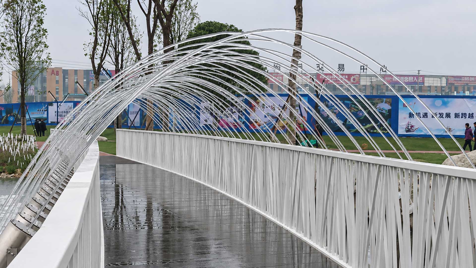
This is why performance should be observed over the entire required trajectory, rather than only at the nozzle exit.
Reynolds Number Is Not the Only Parameter: The Role of Surface Tension
Reynolds number compares inertial and viscous effects. It does not directly describe the balance between inertia and surface tension at the water-air interface.
For that purpose, engineers may also consider the Weber number (We):
We = ρV²D / σ
Where σ is the surface tension of water (N/m).
Surface tension helps resist deformation of the water surface. Disturbances can grow along a liquid jet and contribute to its eventual breakup.
The breakup process depends on several interacting factors, including the initial disturbance level, velocity, jet diameter, viscosity, and surrounding air conditions.
Neither Reynolds number nor Weber number alone gives a universal prediction of the visible continuous length of every fountain nozzle.
For a project requiring a long, clear water arc, numerical calculations provide a starting point. Actual jet observations under representative conditions are also important.
How Does This Apply to Jumping Fountain Jets?
A conventional laminar fountain jet is intended to form a continuous water arc.
A jumping fountain jet adds another function: it intentionally divides the water stream into separate sections.
The hydraulic principle behind producing a smooth stream remains relevant. However, an internal cutting mechanism introduces controlled interruptions to create the jumping effect.
The cutting sequence determines when water is separated. The hydraulic system determines how the water behaves before, during, and after those interruptions.
For a successful jumping effect, engineers should examine three aspects:
Stream quality before cutting. The water should form a sufficiently stable and defined arc under the operating conditions.
Segment formation. The cutting mechanism must produce the intended separation and timing without excessive irregularity.
Recovery after cutting. The water stream should return to its intended continuous shape between cutting events, within the required sequence.
This distinction is important. A jumping jet is not simply an ordinary fountain nozzle with faster pump switching.
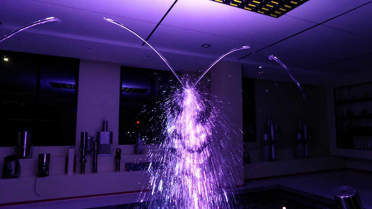
Huaxin’s Jumping Fountain Jets use an internal cutting mechanism to produce separated water segments. Standard, submersible, and laser-illuminated configurations are available for different project layouts.
Does Illumination Change the Hydraulic Requirements?
Lighting changes how a water arc is perceived, but it does not eliminate the need for stable hydraulic conditions.
A smooth water-air interface can help preserve a visually defined illuminated stream. Irregular surfaces, bubbles, and droplets can scatter light and change its appearance.
For this reason, a brighter light source cannot always compensate for an unstable water jet.
A laser-illuminated configuration may improve the visibility of the water effect under certain viewing conditions. Its actual appearance still depends on the interaction of the light source, water quality, flow stability, and surrounding illumination.
Huaxin offers Laminar Fountain Jets in standard, submersible, and laser-illuminated versions.
Selection should be based on the desired visual result and the hydraulic and installation conditions, rather than lighting output alone.
How Should Engineers Evaluate Laminar Jet Performance?
Calculating the Reynolds number is useful during preliminary hydraulic analysis. But practical evaluation should go further.
A structured evaluation can include the following checks.
| Evaluation item | What should be examined? |
|---|---|
| Outlet conditions | Jet diameter, actual flow rate, and operating pressure |
| Water arc | Height, span, landing position, and surface continuity |
| Visual quality | Transparency, surface irregularities, visible droplets |
| Flow stability | Sensitivity to pump fluctuation and air entrainment |
| Operating range | Performance at relevant flow settings |
| Jumping sequence | Segment consistency, timing, and stream recovery |
| Site conditions | Wind exposure, water quality, water level, and viewing conditions |
Testing should be carried out under documented conditions.
A useful test record identifies the nozzle configuration, water temperature, flow rate, pressure measurement location, and observed jet behavior.
For jumping jets, video is particularly valuable because static photographs cannot show cutting timing and recovery reliably.
For project-specific designs, the target height and span also need to be coordinated with the overall fountain layout.
Frequently Asked Engineering Questions
No. Re below 500 is not a universal requirement for commercial laminar fountain jets. A nozzle must be evaluated using its actual hydraulic conditions, flow quality, and required visual performance.
No. A high Reynolds number indicates stronger inertial effects relative to viscous effects. Jet breakup also depends on the initial disturbances, nozzle geometry, surface tension, and surrounding conditions.
Possible causes include entrained air, suspended particles, unstable water supply, outlet contamination, or excessive disturbances within the water stream. These conditions should be investigated individually.
No. Nozzle selection also requires the target jet height, span, outlet diameter, flow rate, pressure conditions, water level, installation arrangement, and any lighting or jumping functions.
Engineering Conclusion
Reynolds number is an important hydraulic parameter, but it should not be treated as a direct measure of fountain water clarity.
A glass-like fountain jet depends on the combined behavior of the nozzle, water supply, free jet, and surrounding environment.
For continuous laminar arcs, the engineering goal is a stable and visually defined stream over the required distance. For jumping jets, consistent segment formation and controlled recovery must also be considered.
The most reliable design approach combines hydraulic calculations, suitable equipment geometry, and practical performance verification.
Huaxin Fountain manufactures laminar and jumping jet systems for commercial fountain projects and programmed water shows. Project-specific equipment selection should be based on the intended effect, operating conditions, and installation requirements.
For further technical and project-planning guidance, visit the Huaxin Fountain Knowledge Center.
Technical References
1. National Institute of Standards and Technology (NIST). Guide to the SI, Chapter 8. Reference for viscosity units and symbols.
2. Sengers, J. V., and Kamgar-Parsi, B. (1984). Representative Equations for the Viscosity of Water Substance. Journal of Physical and Chemical Reference Data, 13(1), 185–205.
3. Falvey, H. T. (1980). Air-Water Flow in Hydraulic Structures. Engineering Monograph No. 41, U.S. Bureau of Reclamation. See the discussion of free-falling water jets.
4. The Effect of Nozzle Design on the Stability and Performance of Turbulent Water Jets. Fire Safety Journal, 1981.
5. A Short Note about the Impact Action of a Water Jet Stabilized by a Coaxial Air Stream in the Air and Underwater. Materials, 2021. Discussion of Reynolds number, Weber number, and liquid-jet breakup.
Technical note: The numerical example in this article is an illustrative calculation, not a certified performance test or acceptance criterion for any specific fountain equipment.
Need Help Selecting a Laminar Fountain Jet?
Share your required jet height, span, installation conditions, and lighting preferences. Huaxin Fountain can help review suitable laminar or jumping jet configurations for your project.
Address
No. 399, Antai Street, Economic Development Zone, Neijiang City, Sichuan Province, China.